Dimensioning Techniques In Engineering Drawing
In this article, we will learn about what is Dimensions and types of Dimensioning systems used in Engineering Drawings.
Dimensions and Dimensioning Systems
A Dimension is a numerical value expressed in appropriate units of measurement and used to define the size, location, orientation, form or other geometric characteristics of a part. In other words, indicating on a drawing, the sizes of the object and the other details essential for its construction and function using lines, numerals, symbols, notes, etc., is called dimensioning.
To construct an object its shape and size must be known. Therefore, an engineering drawing, illustrating the shape, size and relevant details most essential for the construction of the object. The dimensions are given to indicate the sizes of the various features of the object and their location. It is mainly used to know the object size, the name of parts and diameter of the hole etc.
Read Also – 10 Different Types of Lines Used In Engineering Drawing
What you'll learn in this post:
- Elements of Dimensioning
- Units of Dimensions
- Dimensioning common features
- Types of Dimensioning Systems
- Type of Dimensioning
1. Elements of Dimensioning
It includes projection line, leader line, termination of the dimension line, the origin indication, symbols and the dimension itself.
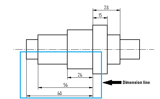
Dimension Line: Dimension line is a continuous thin line. it is indicated by arrowheads, it is drawn parallel to the surface whose length must be indicated.
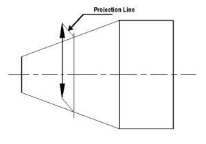
Projection or Extension Line:A projection line or extension line, it is a thin line. It is drawn perpendicular to the surface which is to be dimensioned. The projection line slightly extends than the dimension line.
Constructions line:A construction line is a thin line drawn to indicate the dimension line. The construction line is extended slightly beyond the point intersection.
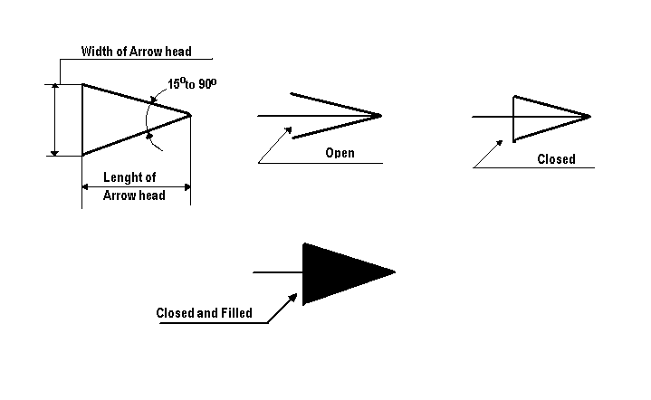
Arrowheads: Arrowheads are used to indicate the dimension line. Usually, the arrowhead must include angles of a minimum of 15°. The Arrowhead may be open or close or closed and filled.
Leader or Pointer Lines:These are thin continuous lines drawn from a dimension figure to the feature to which it refers. Leader line is drawn may be 30° or 60° to the bottom of dimensions.
Dimension Figure: These are drawn may be vertical or inclined to indicate the height of the dimension figure.
2. Units of Dimensions
The dimension unit is millimetre. The unit of the dimension is omitted while writing the dimension fig. and a footnote stating "ALL DIMENSIONS ARE IN MM" is written at the prominent place on the drawing sheet.
3. Dimensioning common features
Dimensioning diameters
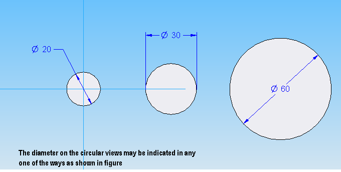
Circular features like cylindrical parts like shafts, pipes, rods or any other round shape are always dimensioned by indicating their diameter. Because it is easily measured.
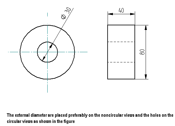
The diameter is indicated by the symbol ∅. The diameters on the circular objects may be indicated in any one of the following ways as shown in fig.
Dimensioning Radius
The curved, fillets and round figures are shown in drawings by arcs or circles. The dimensioning is done by giving radii.
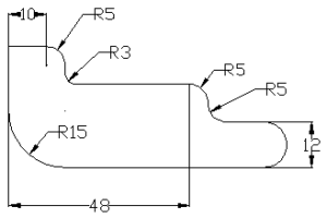
The measured radius is indicated by letter R. The dimension line is drawn radial with the arrowhead touching the arc.
When the centre is located by the projection lines, the centre shall be marked by a clear dot and the arrowhead may be reversed.
When the centre of the arc falls outside the drawing limit, the dimension line of the radius should be broken or interrupted according to whether or not it located the centres.
Dimensioning Arcs
When dimensioning the length of an arc the dimension figure identified by symbol being written above the dimension.
Dimensioning Chords
It is a linear distance between any two points of an arc. And it is dimensioned as shown in the figure.
Dimensioning Angles
The angles are dimensioned in the same manner as that of linear dimensions.
4. Types of Dimensioning systems:
There are two types of dimensioning systems one is Aligned system and another is Unidirectional system.
Aligned System
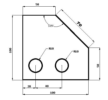
In this type of dimensioning systems, Dimensions are placed above the dimension lines which are drawn without any break and written parallel to them.
That they may be read from the bottom or any other side of the drawing sheet. Dimensions are placed in the middle and on top of the dimension lines.
Unidirectional System
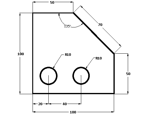
In this type of dimensioning system, dimensions are placed in such a way that they can be read from the bottom edge of the drawing sheet. Dimensions are inserts by breaking the dimension lines at the middle.
Dimensions must be drawn like this
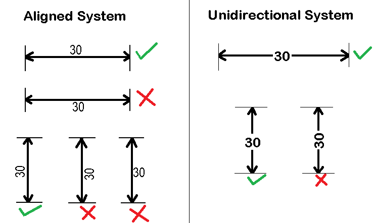
Use only one placing of dimension system in one entire drawing. The aligned and unidirectional system should not be mixed together in one drawing.
5. Types of Dimensioning
The different methods, arrangement and the indication of dimension are
- Chain Dimensioning
- Parallel Dimensioning
- Combined Dimensioning
- Progressive Dimensioning
- Dimensioning by Co-ordinates
- Equidistant Dimensioning
- Repeated Dimensions
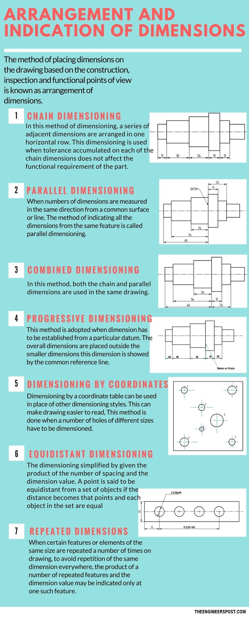
Chain Dimensions
Chain dimensioning is a dimensioning system that dimensions from point to point. Or it is a series of adjacent dimensions are arranged in one horizontal row. When chain dimensioning is used the location of one feature is based on the location of the previous feature from which it is dimensioned.
Chain dimensioning is used when it is important that two features are
Parallel Dimensioning
When the number of dimensions is measured in the same direction from a common surface or line. The method of indicating all the dimensions from the same feature is called parallel dimensioning. The dimension lines are parallel to each other and equally spaced.
Combined Dimensioning
In this method, both the chain and parallel dimensions are used in the same drawing.
Progressive Dimensioning
This method is adopted when dimension has to be established from a particular datum. The overall dimensions are placed outside the smaller dimensions this dimension is showed by the common reference line.
Dimensioning by Coordinates
Dimensioning by a coordinate table can be used in place of other dimensioning styles. This can make drawing easier to read, this method is done when a number of holes of different sizes have to be dimensioned.
Equidistant Dimensioning
The dimensioning simplified by given the product of the number of spacing and the dimension value. A point is said to be equidistant from a set of objects if the distance becomes that points and each object in the set are equal.
Repeated Dimensions
When certain features or elements of the same size are repeated a number of times on drawing, to avoid repetition of the same dimension everywhere, the product of a number of repeated features and the dimensions value may be indicated only at one such feature.
Conclusion
Dimensions are very important in the engineering field and it is the most useful skill in an industry that will help you to read any type of engineering drawing without any confusion. Learning and understanding of how dimensions are mentioned are very easy if you focus on learning.
Download PDF of this article

That's it, thanks for reading. hey if you like our article on "dimensions and types of the
Read more on this blog:
- Shaper machine and types of shaper machine
- Planner machine and types of planner machine
- Lathe machine and its operations
Checkout this link for Auto CAD works in India:
India CAD Works
References:
https://www.enggwave.com/dimensioning-arrangements
Dimensioning Techniques In Engineering Drawing
Source: https://www.theengineerspost.com/dimensioning-systems/
Posted by: hiserotile1968.blogspot.com

0 Response to "Dimensioning Techniques In Engineering Drawing"
Post a Comment